Quick Start Guide - SE (LEGACY)
SmartyPI SE, PCB Revisions 1.1 - 1.4
What’s in the box
When you receive your SmartyPi parcel it will contain the following:
- SmartyPi SE PCB.
- GPIO to SmartyPi adapter. (Fixed to SE PCB – This connects SmartyPi to the Raspberry Pi)
- 2x PCB Extenders. (Optional for mounting SE PCB)
- USB Cable. (USB-A to USB Micro-B)
- SD Card adapter containing a Micro-SD card which is ready loaded with the latest Raspberry Pi image.
- Heat Sink for attaching to your Raspberry Pi.
- 4x M2.5 nuts to secure Raspberry Pi to SE PCB.
- If you have purchased adapter PCBs for other cabinets, or additional items, these will be included in your package.
Before we begin…
The only additional component you will require is a Raspberry Pi 4B, SmartyPi is compatible with all RAM versions. Check the guide section of SmartyPi.co.uk for the latest setup and configuration information.
All SmartyPi PCBs and parts (USB Cable, & SD Cards) are checked in a game cabinet before shipping. I have full confidence that your out of box experience will be straightforward and after following this guide, you will be up and running, playing games. While SmartyPi is intended as a replacement for the original game PCB, it will not fix a cabinet that has poor controls or has bad colours on the monitor. Audio is still be routed through the original cabinet’s audio amplifier circuit, the only item SmartyPi replaces is a broken game PCB. Now that’s cleared up, let’s get on with the setup.
Recommended setup procedure
You need to complete assembly of SmartyPi by connecting your Raspberry Pi, adding the SD card, and fixing the Heatsink. Let’s complete this in the following order.
- Gently remove the GPIO to SmartyPi adapter (highlighted in photo at end of document) It will lift upwards if you wiggle it back and forth.
- Remove the Micro-SD card from the adapter you received with SmartyPi and push it into the Raspberry Pi Micro-SD slot. If we are looking at the Raspberry Pi from the top side, the green sticker on the SD card will be facing upwards when inserted.
- Place the Raspberry Pi onto the threads from the hex nuts, you may need to loosen the screws from the underside. Once the Pi is sitting correctly, place the Nuts (x4) onto the threads and finger tighten them (clockwise), take your GPIO adapter and align it to the pins on the Pi and the header on the SmartyPi SE PCB. Press it down until it is making a snug fit and against the pins of both the Pi and Smarty. If necessary, tighten the nuts on the hex posts. Now we can attach the heatsink.
- The Heatsink is larger than the surface we are connecting it to, in our case the heatsink will sit directly on the CPU but also cover various other components of the Pi. Remove the tape from the underside of the heatsink and place it over the Pi, it is a snug fit against the GPIO connector and other connectors of the Pi. Press down over the centre of the heat sink for 30 seconds making sure it is sitting flat over the CPU.
- Plug the supplied USB cable between the Raspberry Pi and the microcontroller (As shown on the SmartyPi silkscreen labelling. Do not force the cable into the microcontroller port, it will only fit one way round and should be gently pushed into the socket. I recommend plugging the cable into the Raspberry Pi first and then the microcontroller.
- Your system will come preconfigured but if you would like to change settings, this is the process:
- Remove the configuration MicroSD card, the SD card is spring loaded, press it inwards and it should spring outwards and be released.
- Take the MicroSD and connect it to a computer, use the supplied SD card adapter if needed. In the root of the drive is a file called setup.txt open this in your text editor of choice. There are various parameters that can be adjusted, at the time of release the config file is at revision 2.4.
- The options which can be configured are as follows:
Cab=OR (This option selects the Cabinet SmartyPi will be used in and calibrates controls to suit.)
SwitchGames=FALSE (If you are entitled to play different game ROMs set this to TRUE.)
Outputs=ALL (Decides which output signals are used.)
GameList=ORc (Chooses the game list and order they will play)
CG1=CB (Custom Game 1 – Used with the Custom GameList=CU parameter.)
-> CG12=TOR (Custom Game 12 – Used with the Custom GameList=CU parameter.)
Unused CG parameters should =NA
Read the list of available options for each parameter and alter, as needed. Once happy with the options, save the file. Eject the MicroSD card from your computer and place it back into SmartyPi.
You should now mount SmartyPi in the cabinet. Turn the power to your cabinet off. If you have an original game PCB, I suggest you remove it, and stored in a safe place so no chance of accidental damage can occur while SmartyPi is being wired in and setup. Using the supplied PCB Extender arms, SmartyPi can be mounted and fixed to the original hole positions an original game PCB would occupy.
Before plugging any connectors to SmartyPi, you must check your cabinets 5 Volt power supply level. With the original game PCB removed, turn the cabinet on and measure the 5V DC form the white and yellow power connectors of the original game, adjust your supply to be as close to 5 Volts DC as possible, a reading from 5.00 to 5.09 DC is acceptable and suitable for use in SmartyPi. If you do not follow this guidance, and the power supply it is set higher that 5.2 volts, you may destroy the Raspberry Pi and other circuits on the PCB, providing more disappointment than when your original PCB breaks! I cannot accept responsibility for damage caused by over voltage. If you do not know how to check and adjust the power supply, please ask and I will guide you through. Once you have checked and set your power supply, turn power to the cabinet off.
Plug in the connectors to SmartyPi. Use one of the Power connectors (the second one you may have can be left disconnected and loose.) Connect the Video and Audio connectors. You may have a four or six pin connector for audio, if it has four pins, follow the placement as shown in the PCB silkscreen (Connect from the left side, leaving two unused pins on the right side as you look at the PCB, with the text in correct reading orientation.) Finally connect the two I/O connectors, the fifty (50) pin and/or twenty (20) pin black connectors. These are ‘keyed’ and can only be inserted in one orientation. Once all connectors are in place, you can power on the cabinet on.
You should see the SmartyPi logo screen for a short while, followed by having the first game in the selected list load. Controls should be configured to work, if entitled, use the game switch button (default is cab Service button) to cycle through games. You may need to make minor monitor adjustments for size and position, brightness, and vertical sync to obtain a stable picture but is not needed in most situations.
If you don’t see or hear your game playing 30 seconds after turning you cab on, power it off and check all connections are correctly made. For further detailed instructions & troubleshooting, look in the ‘guide’ section at smartypi.co.uk
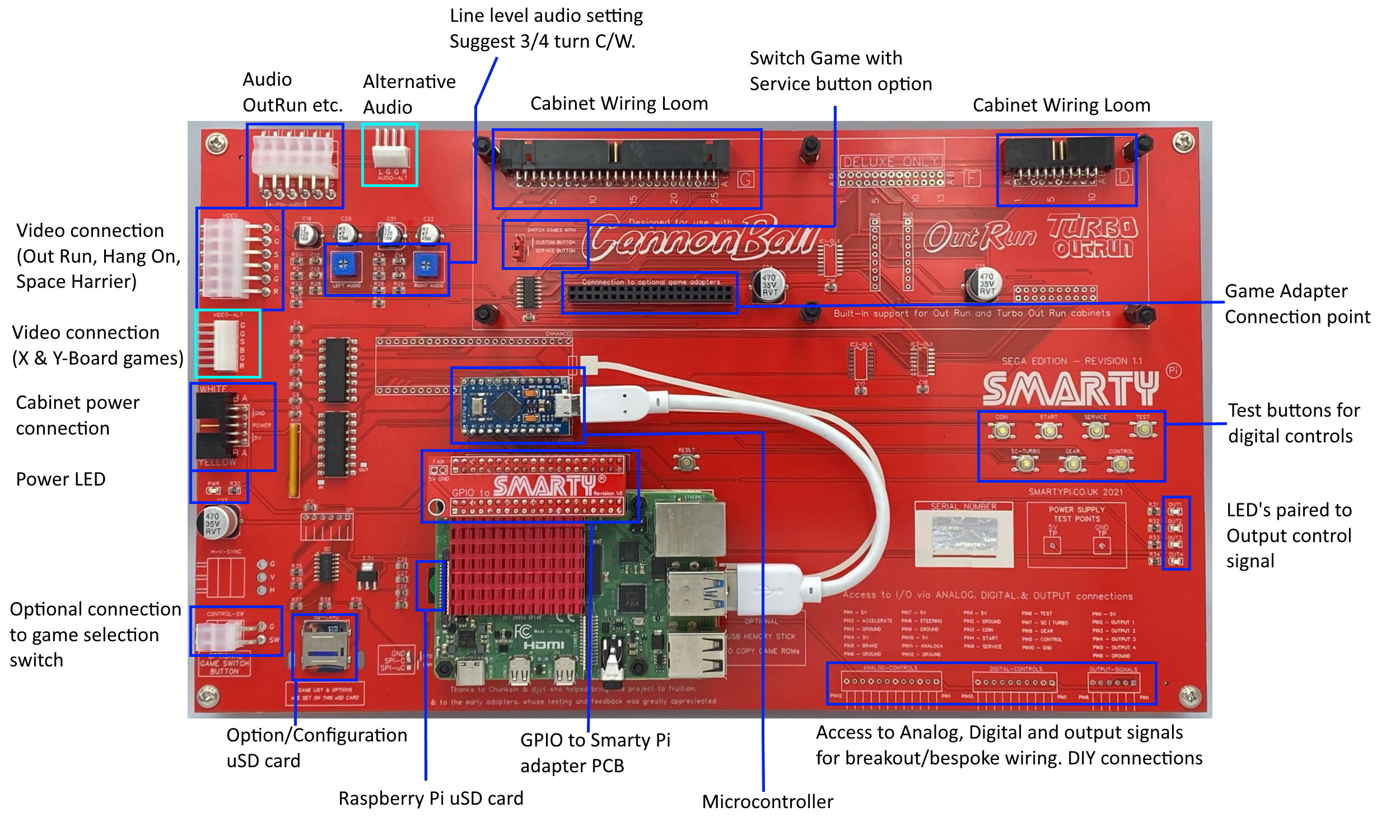
SmartyPi component locations
Further information can be found at smartypi.co.uk or you can contact me via email at smartypi.arcade@gmail.com Other SmartyPi users may be able to help with technical issues, they can be found on the UKvAc forum, or on Facebook in the Out Run Arcade Owners and Enthusiasts, or SmartyPi User’s groups.
Display prices in:GBP